How to assemble an electric air compressor
A simple air compressor, with which you can perform paint work or pump up car tires, can be made with your own hands from scrap materials. A homemade compressor will work no worse than its factory counterparts, and the cost of its manufacture will be minimal.
Content
Autocompressor upgrade
You can make a mini compressor for connecting a spray gun or airbrush from an automobile pump, having improved it a little. Modernization of the compressor will increase its power (performance) and will consist in adapting it to a voltage of 220 V (instead of 12 V), connecting the device to the receiver and installing automation.
Adaptation of the device for voltage 220 V
To connect the pump to a 220 V network, you need to find any power supply unit (PSU), the output of which will be 12 V and a suitable for the device current strength.

You can find out the value of the current consumed by the device, if you look at its nameplate. In this case, the power supply from the PC (see figure above) in terms of current and voltage will be quite enough.

So, if you insert the plug of the power cord into the power supply of the PC and turn it on, nothing will happen. This is due to the fact that the PSU will not turn on until it receives a signal from the PC. To simulate the inclusion of the PC, on the connector coming out of the PSU, you need insert jumper. It will be necessary to find among the many conductors one wire green, and the second black, as shown in the following photo.

These wires can be cut and twisted, but it is better to short them with a jumper.

Further, it is necessary to find at the output of the power supply 2 more wires: one yellow, it will be “+”, and one black with polarity “-”. You can take any wires of these colors from any bundle of conductors.
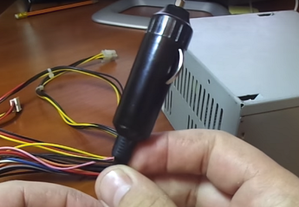
Since the autopump has cigarette lighter plugthen it can be cut off and connect the device with the appropriate color wires from the power supply.

But it would be better if you buy a car cigarette lighter and connect it to the power supply, and then connect the device itself using a standard plug.
From the cigarette lighter comes out 3 wires: red - “+”, black - “-” and yellow - “+”, designed to connect the LED. Connect the conductors to the cigarette lighter, observing the polarity (see photo below).

If you insert the plug from the device into the cigarette lighter, you will get an air electric 220 V compressor that can not only inflate tires, but also work with an airbrush.
Connection of additional elements
To connect the device to the receiver, it is necessary to assemble the structure shown in the diagram below.

The following elements are a part of this binding.
- Crosshaving all exits with BP1 / 2. Marking means: “BP” - internal thread, “1/2” - thread diameter in inches.
- Tee, has all exits with NR1 / 2 (“NR” - external thread).
- Valves in the amount of 2 pcs. (BP1 / 2 - BP1 / 2). Designed to block the movement of air in both directions.Double marking means that there is an internal thread on both sides of the valve.
- Check valve. Designed to pass air in one direction only. You can install a simple spring valve BP1 / 2 - BP1 / 2. If you plan to work with a pressure of 6-7 bar, then you must select a check valve that does not have plastic parts.

- Straight nipple, is an adapter having 2 external threads (HP1 / 2).
- Transition nipple NR1 / 2 - NR1 / 4. Allows you to switch from one external thread diameter to another.
- Extension (60 mm) HP1 / 2 - HP1 / 2. This is the same nipple, only straight. That is, the thread at both its ends has the same diameter.
- Coupling transition. It is an adapter from internal thread of one diameter to internal thread with another. In this case, from BP1 / 2 to BP1 / 8.
- Teehaving all the outlets already threaded with HP1 / 8.
- Straight coupling BP1 / 8 - BP1 / 8. It has 2 identical internal threads.
- Hose adapter HP1 / 8.
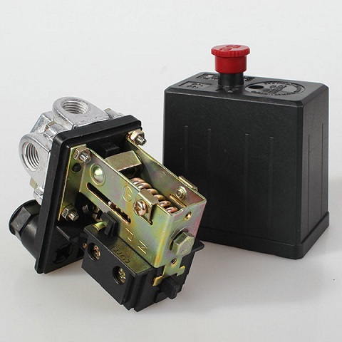
- Pressure regulator (pressure switch) with water-oil separator. The pressure switch allows you to maintain the air pressure in the receiver is not lower than the minimum and not higher than the maximum allowable level.You can also install a dehumidifier if the unit will be used as a pump for tire inflation. When using the unit for painting the installation of a moisture separator is a prerequisite.


The above scheme of tying involves 2 output fittings: the first for air outlet to the spray gun (airbrush), and the second - for tire inflation.
- Transition nipple NR1 / 4 - NR1 / 8.
- Knob (НР1 / 4 - ВР1 / 8), is an adapter from the larger diameter of the external thread to the smaller diameter of the internal thread.
- Manometers. These devices allow you to visually monitor the level of air pressure in the receiver and the flow into the line.
When assembling all the elements you need use thread sealantFor example, fum-tape. Pressure gauges can be connected through high pressure hose trim. The last should be tightened on adapters and fix with clamps.

Gauges can be screwed directly to the thread, without the use of hoses, if you do not want to display them on the front panel of the unit.
How does the compressor strapping assembled according to the scheme look like is shown in the following photo.

The receiver for the autocompressor can be made of a metal pipe of large diameter, welded on both sides, a fire extinguisher or a gas cylinder. If the compressor is supposed to work only with an airbrush, then a conventional tubeless wheel from a car can serve as a receiver.
Important! When assembling the tank for the receiver, one should take into account the fact that the autopump can work no more than 10 minutes. continuously. Accordingly, the volume of the receiver should be small (about 20 liters) so that the device can raise the air pressure in it to the required level before 10 minutes have passed.
A simple version of the unit of a fire extinguisher / gas cylinder
It is rather simple to make a compressor with your own hands using as a storage tank for the air of a fire extinguisher or a gas cylinder. For example, the compressor unit itself, if you want to make a powerful unit, you can take from zilovsky compressor. But first, it needs a little refinement.
- Drill one hole in the wall of the compressor through which will pour oil into the crankcase. Which way you do it doesn't matter. The main thing is that it is located below the axis of the crankshaft approximately 10 mm. In this hole M8 thread is cut under the plug.
- A fitting is connected to the cover covering the rear bearing. An oil resistant hose is put on it, which will be connected to the lubrication system in the form of an expansion tank (you can take a tank for brake fluid from a car) installed at the level of cylinders.


- In order to allow excess oil to get into the expansion tank during operation of the unit, remove the valve (7) Oil line (see figure below), located under the bearing cap.


- Next, drill holes in the connecting rods and liners, as shown in the following figure.

Drill 2 holes in each connecting rod (assembled, with inserts) and 1 hole in each connecting rod cap.

When the unit is operating, the oil in the crankcase will flow through these openings to the liners and reduce friction between them and the crankshaft.

Further, the receiver and piping with automation is connected to the compressor. How to do it was considered in the previous paragraph.
If you take for receiver fire extinguisher, first you need to remove all the extra parts from it, leaving only the container and the cover.

In a cast iron lid, ¼ inch threads should be cut. Also under the cast iron lid, you must lay a rubber gasket, if it was not there, and screw the lid using fum-tape to seal the thread.
Next, screw the adapter with 1 / 4HP to 1 / 2HP into the cover and install the crosspiece.

Actions to connect all the elements of the strapping were described at the beginning of the article. But, since this unit is made of ZIL 130 compressor, and is more powerful than previously considered, it will be necessary to install a safety (emergency) valve. He will release the excess pressure, if for some reason the automation does not work.

You can also make gas cylinder compressor. But first you need to release the gas from the cylinder, then twist the valve. Next, you need to completely fill the cylinder with water to remove residual gas. The cylinder should be rinsed with water several times and, if possible, dried. Usually a gas burner is installed under the cylinder and all moisture is evaporated from the container.
A futorka is screwed into the hole where the valve was placed, and the crosspiece is fastened into it, to which the automation and all the harness are attached.In the lower part of the cylinder, it is necessary to drill a hole and weld a condensate drain to it. At the fitting, you can install a regular water tap.
For mounting on the receiver of the engine and compressor unit is made frame made of metal angle. Pre-welded to the cylinder mounting bolts. The frame will be attached to them (see photo below).

Important! The engine for this unit must have a power of about 1.3 -2.2 kW.
You can also make a compressor for tire inflation from chainsawwhich is beyond repair. The device is made from the engine, that is, from the piston unit: the output hose is connected through a non-return valve instead of a spark plug, and the hole for the exhaust gases is blocked. To rotate the crankshaft, you can use either an electric motor or an ordinary electric drill.


Compressor from the refrigerator
The air compressor made from the refrigerator, more precisely, from its unit, is the most silent. But you should know that such a device does not differ high performance. With it, you can only pump up the car's tires or work with an airbrush. For normal operation of various pneumatic tools (screwdriver, grinder, spray gun, etc.), the performance of this unit is not enough, even if you connect a large volume receiver to it. Although on the Internet you can find designs consisting of two or three compressors connected in series, connected to a large receiver.
So, the unit, taken from the refrigerator, has starting relay with mains cord. Also, 3 copper tubes come out of the apparatus. Two of them are designed for air inlet and outlet, and the third (sealed) for oil filling. If you turn on the device for a short time, you can determine which of the two tubes sucks air, and from which it is blown out.
The following figure shows how to assemble the entire structure, consisting of a unit, a receiver and a pressure regulator with a pressure gauge.

On the inlet tube is installed air filter to prevent dust from entering the unit.To automate the process of pumping air, you can install automation in the form of pressostat.
High pressure compressor do it yourself
High pressure compressor (HP) is made from two-stage compressor head AK-150.


As a drive you can take 380 V motor with 4 kW. The transfer of rotation of the motor shaft to the piston shaft is carried out with the help of an eccentric, which also serves as a drive for a plunger-type oil pump. It creates an oil pressure of about 2 kgf / cm2.
Coming from the last stage, compressed air enters through the adapter with the installed pressure gauge into the fitting of the liter cylinder, which is installed in its lower part. A condensate drain valve is also installed here. The balloon is filled with ground glass and performs the role of a moisture separator.

Air is released from the top of the cylinder through a finger socket. Compressor cooling is watery. After 45 minutes unit operation water is heated to 70 degrees. The author of this unit claims that during this time it is possible to pump 1 cylinder per 8 liters and 2 cylinders per 4 liters up to 260 atm.

/rating_on.png)


